Mirror lenses and telescopes, also called reflex or catadioptric lenses (henceforth just “mirror lenses” for brevity), are a combination of curved mirrors and lenses. They are commonly used in reflecting telescopes and super-telephoto photographic lenses. They are known for being light and compact, but they have a mixed reputation for sometimes delivering poor image quality and contrast, creating a soft, washed-out look with poor colors.
This effect is often attributed to various causes (diffraction, vignette, stray light, etc) that turn out not to fully explain the problem, and when these causes are corrected, the problem remains. The real cause is that the mirrors reflect undesired light from behind the lens (e.g. light scattered off a camera sensor) back into the image. The result is that the image is polluted by a dim haze of defocused stray light caused by the sensor’s own reflectivity, akin to an optical feedback loop.
The good news is that the detrimental retro-reflections come from parts of the mirrors that are actually “dead spots,” not illuminated by desired light from the object in front of the lens. Therefore, they are easily prevented, resulting in a notable improvement in contrast and color accuracy without otherwise affecting the image. I have successfully modified a variety of lenses and telescopes (of the common Cassegrain designs) to block and absorb sensor reflections, with excellent results. The same technique is easily applicable to essentially every mirror lens design including reflecting telescopes.
Although this improvement is based on a simple principle anyone can understand, I have found no evidence that anyone in the nearly 400-year history of reflecting and catadioptric optics has grasped how to prevent the retro-reflections inherent in these designs. It is exciting to have a simple way to modify existing lenses for superior image quality, but far more impactful to incorporate this improvement into the design process. There are many, and much more effective, ways to improve lens designs than to retrofit lenses after manufacture. It is clear that with this discovery, reflecting and catadioptric optics are potentially capable of substantially better results than previously achieved. Given that these designs are indispensable to a wide variety of important applications (e.g. space telescopes, microscopes, VR headsets, navigation systems, photometry, surveillance systems, night-vision devices, medical devices, and many more) this is obviously a significant discovery.
Mirror lenses and telescopes come in a wide variety of configurations, and there are correspondingly many edge-cases and variations to consider. This article goes into some depth on many of these, but I have sought to avoid mathematics or other areas a person of average education or experience is not prepared to understand. My goal is for everyone to understand the principles of the discovery.
Synopsis: Blacken a Spot on the Secondary Mirror
This is a long article, but I can summarize. When you look into the rear of a mirror lens, you’ll see your own reflection. This means that the lens is reflecting light from the rear, which is a problem. Ideally, lenses only transmit light from a specific field of view: the object in front of them at which they are aimed. Ideally, they absorb or block all other light, including reflections from their interior and rear.
You’ll note that as you tilt and angle the lens from side to side, an area in the center of the rear-facing mirror reflects your eye, but never reflects any light from the front—you can never “see through” the lens in that area. That’s the indication that this circle is a useless dead spot, never involved in focusing light coming from the lens’s intended field of view.
If you blacken the dead spot that reflects light from the rear but none from the front, you’ll improve the lens’s contrast by absorbing the stray light bouncing off the camera’s sensor. It may seem too good to be true, but it’s really that simple.
Mirror Lens Design Fundamentals
The most common mirror lens and telescope designs are quite simple. They are made of a pair of curved mirrors, usually held within a tube or struts. Light enters the front, reflects back and forth between the mirrors, then exits through a hole in the rear mirror to form an image. The curvature of the mirrors concentrates the light, and there are usually some corrective optics as well to improve image quality. This category of mirror lenses is called Cassegrain; here is a light path diagram from Krishnavedala on Wikimedia Commons (CC BY-SA 4.0)

Another important design is the Newtonian, mostly used in telescopes. Instead of bouncing directly backwards, light reflects sideways through the side wall of the scope to form an image. Here is a similar light path diagram from Krishnavedala on Wikimedia Commons under the same license.
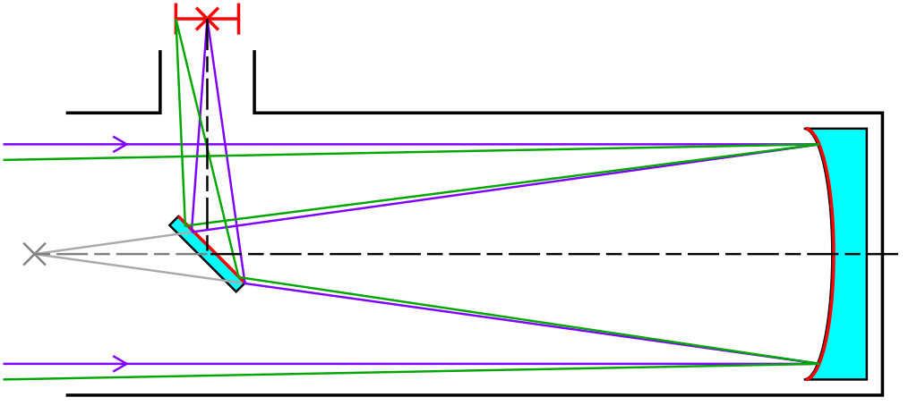
There are many, many variations on these schemes, but the vast majority of mirror lenses and telescopes are exactly as described, or not much different, at least in principle. This includes the most important and expensive telescopes such as the Hubble Space Telescope, for example.
One characteristic of these designs is a central obstruction, a blockage in the middle of the lens, casting a shadow down its middle. This causes a variety of effects peculiar to mirror lenses, including “donut-shaped bokeh,” a loss of brightness, and diffraction among other things. Diffraction is particularly relevant to this article—more on this later.
The Mirror Lens Hot Spot Problem and its Cause
Mirror lenses have some attractive properties for super-telephoto photography, but they often produce washed-out images with a hazy glare, especially in adverse lighting. A typical example of adverse lighting is an image taken against or near the sky or another large, bright light source, such as a backlit body of water or the wall of a building. In my own photography, mostly of birds using a Fujifilm camera, I consistently found that this glare is a harsh teal-green color cast that’s brighter in the center of the image. It reduces contrast, distorts colors, muddies shadows, tricks the camera’s auto white-balance, and generally makes everything look ugly; and like many photographers, I found it’s hard to correct in post-processing.
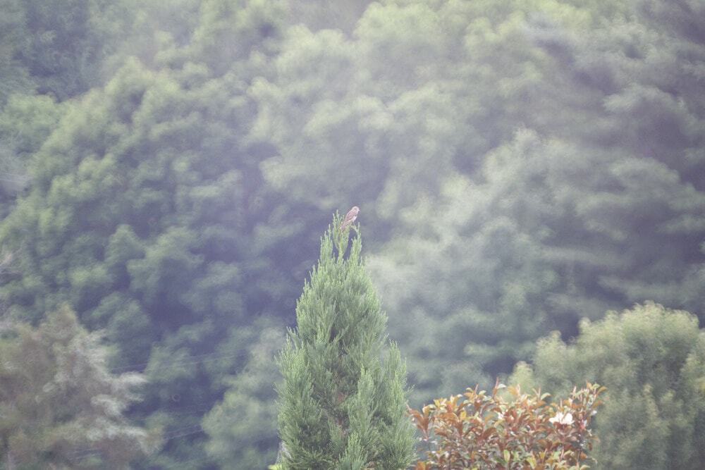
This problem is not limited to terrestrial photography. From my own limited dabbling in astronomical imaging, and lots of study of other astronomers’ images, I see the same effect in reflector telescopes that I know well from my bird photography.
Studying this effect, and the usual dead-end journey of trying to understand and correct it is instructive, so this section will be a bit long in order to ensure that common explanations that might serve as alternatives to this article’s main thesis are considered and contextualized in depth.
Photography forums have many discussions about the way mirror lenses wash out images with a harsh glare effect, and what causes it. One common suggestion is that it’s diffraction from the central obstruction. Light going past an edge doesn’t just stream straight past. The light that passes close to the edge bends around it a little. The edge of the central obstruction therefore scatters some light across the image, and forum discussions often blame this for causing the hazy glare and low contrast. The usual response goes something like “that’s just inherent to the design of mirror lenses, caused by the central obstruction, you can’t overcome the laws of physics.”
However, this glare is not simply low contrast caused by diffraction from the obstruction. Diffraction is real, but when you do the math, its effect on contrast is weaker and different from the observed glare. To quote Wikipedia, diffraction “has the effect of lowering image contrast when imaging broad features” and High Point Scientific describes obstruction-related loss of image quality as “very subtle, so most amateur astronomers do not even notice or care about this detail.” And diffraction-related loss of contrast is neither lighting-dependent, blue-colored, nor concentrated brightly near the center of the image. In fact, it should be possible to correct it with the contrast slider in any image editing program, but although this this corrects low contrast, it actually emphasizes the unevenly concentrated glare, making it more obvious. This glare is additional to the overall low contrast—a separate effect.
Let’s turn our attention to the way this glare is centrally concentrated. Some photographers describe mirror lenses as having a very strong “vignette” effect—a falloff in brightness towards the edge. Indeed, most lenses are dimmer at the edges of the image, catadioptric or otherwise. However, careful observation shows the glare is no ordinary vignette. An optical vignette has a relatively smooth and continuous falloff in brightness, but mirror lenses have a flat bright spot in the center with strongly defined edges. And again, vignette correction controls in image editing programs don’t correct it, they actually emphasize its edges. Here is an example, with contrast and exposure artificially changed to highlight the brightness and clearly defined edges of the central spot of glare.
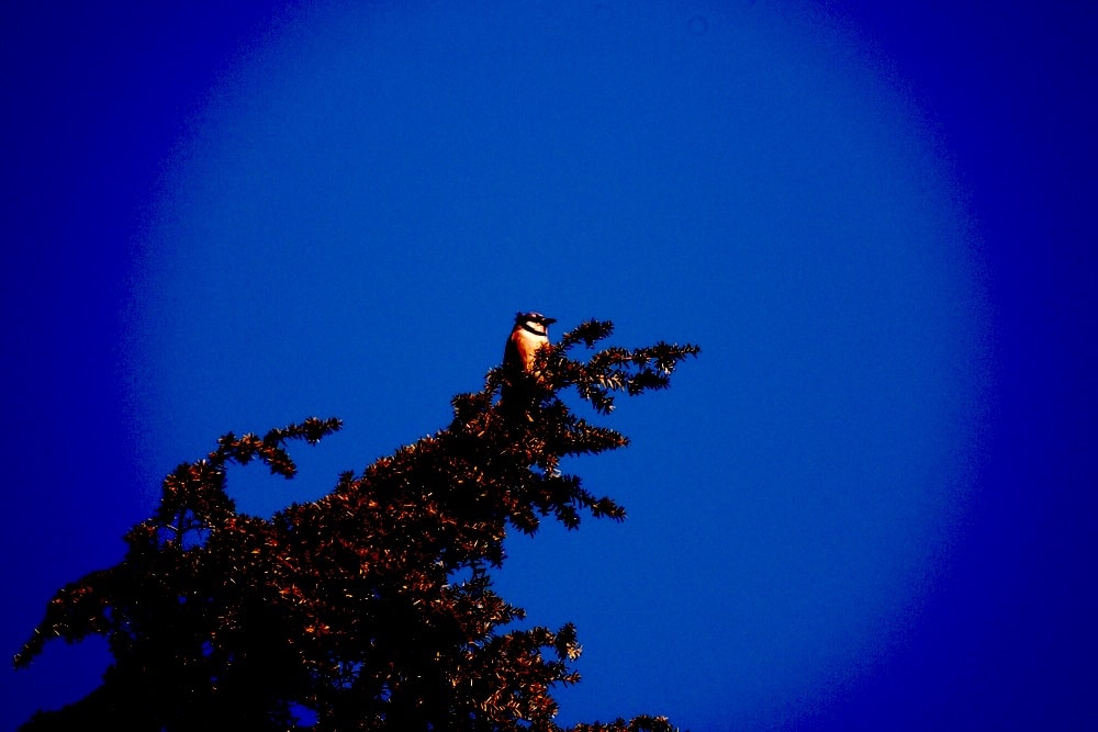
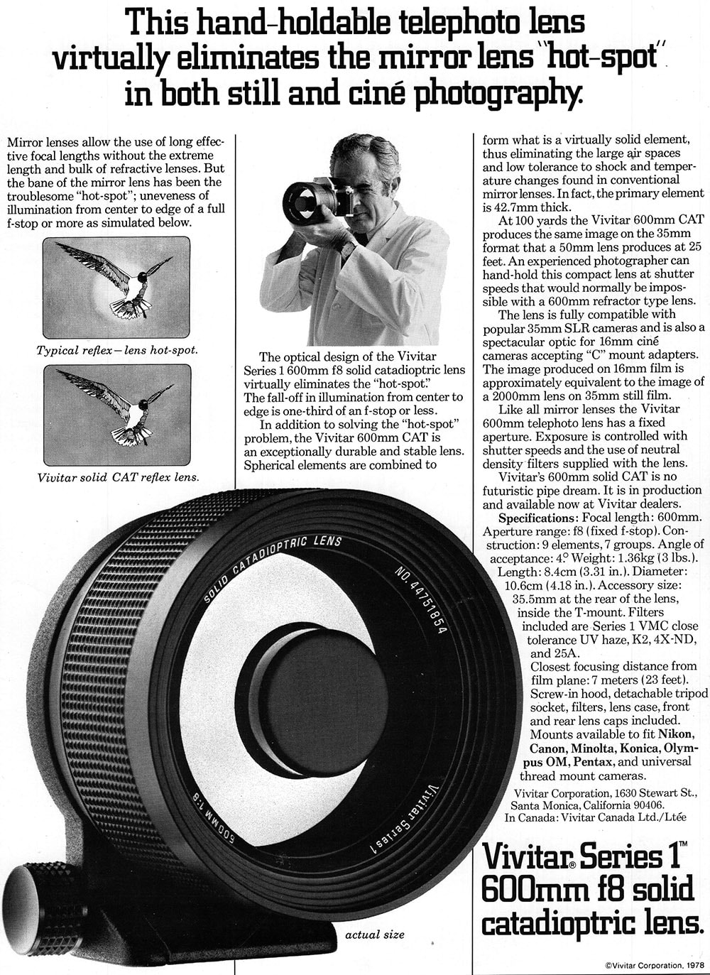
This glare is sometimes called a “hot spot,” which is a more accurate description than calling it vignette. Here is a 1978 advertisement for the Vivitar Solid Catadioptric mirror lens emphasizing the hot spot.
Another possible explanation for the hot spot is poorly controlled stray light. Mirror lenses and telescopes are notoriously prone to unwanted light coming from outside the image frame, and the hot spot certainly appears to worsen when the lens is pointed near bright areas such as the sky. This would be consistent with the stray light theory.
Indeed, the more you think about stray light, the more likely it seems as the cause of the hot spot, especially when you have a collection including samples of nearly every mirror lens ever made, as I do. My endless fascination with mirror lenses and interest in trying hundreds of them taught me that the difference in stray light control between them is often night-and-day. In fact, most mirror lenses just aren’t made to block stray light well enough, and the poorly made ones have much worse hot spots and glare. Working from this theory, I learned as much as I could about stray light control by studying a variety of sources, and applying my knowledge by modifying dozens of lenses. What I found was partially encouraging: I could dramatically improve the image quality of a lot of cheap mirror lenses by adding baffles and flocking where needed. However, I determined that the best mirror lenses already had extremely effective stray light control, essentially eliminating it completely—and yet they still had a hot spot and hazy glare, to some extent.
And again, puzzlingly, the hot spot I was seeing always had a bluish haze color, no matter what light sources were in front of the lens. Glare from stray light isn’t always the same color, and there is nothing in a mirror lens that would selectively pass stray light at some wavelengths but not others. My experiences modifying mirror lenses to fix poorly controlled stray light taught me that the glare from stray light is the color of the stray light, not uniformly bluish haze. Again, just like diffraction and vignette, this effect is separate and additional to stray light, and remains when stray light is corrected.
One day I was looking into the rear of a mirror lens for the hundredth time, and suddenly noticed for the first time that what I saw—a clear, bright image of my own face—was a problem. A lens should show an image of what’s in front of it, not what’s behind it. When the lens is placed on a digital camera, a brightly illuminated, reflective, bluish-green sensor is behind it. I knew immediately that I had found the cause of the problem, and I knew what to call it: ghosting.
Ghosting is a well-known problem, and it’s essential to consider during lens design. Many lenses have been redesigned to cure ghosting, especially during the transition to digital photography around the turn of the 21st century. A famous example is the Tamron 90mm f/2.5 macro lens, model 52B, whose flattish rear element causes a notorious “blue dot” when used on digital cameras. The improved model 72B solves this with a curved rear element and better coatings to reduce reflections. You can find many other examples of lens redesigns to “optimize for digital” by reducing ghost reflections from rear-facing surfaces. Ironically, mirror lenses have a nearly perfectly reflective rear-facing element, but I was not able to find much literature on the resulting ghost images; the phenomenon seems to be mostly overlooked in the context of mirror lenses, even though the design inherently causes much worse ghosting. The clearest explanation I have found to date comes from a Sigma mirror lens instruction manual:
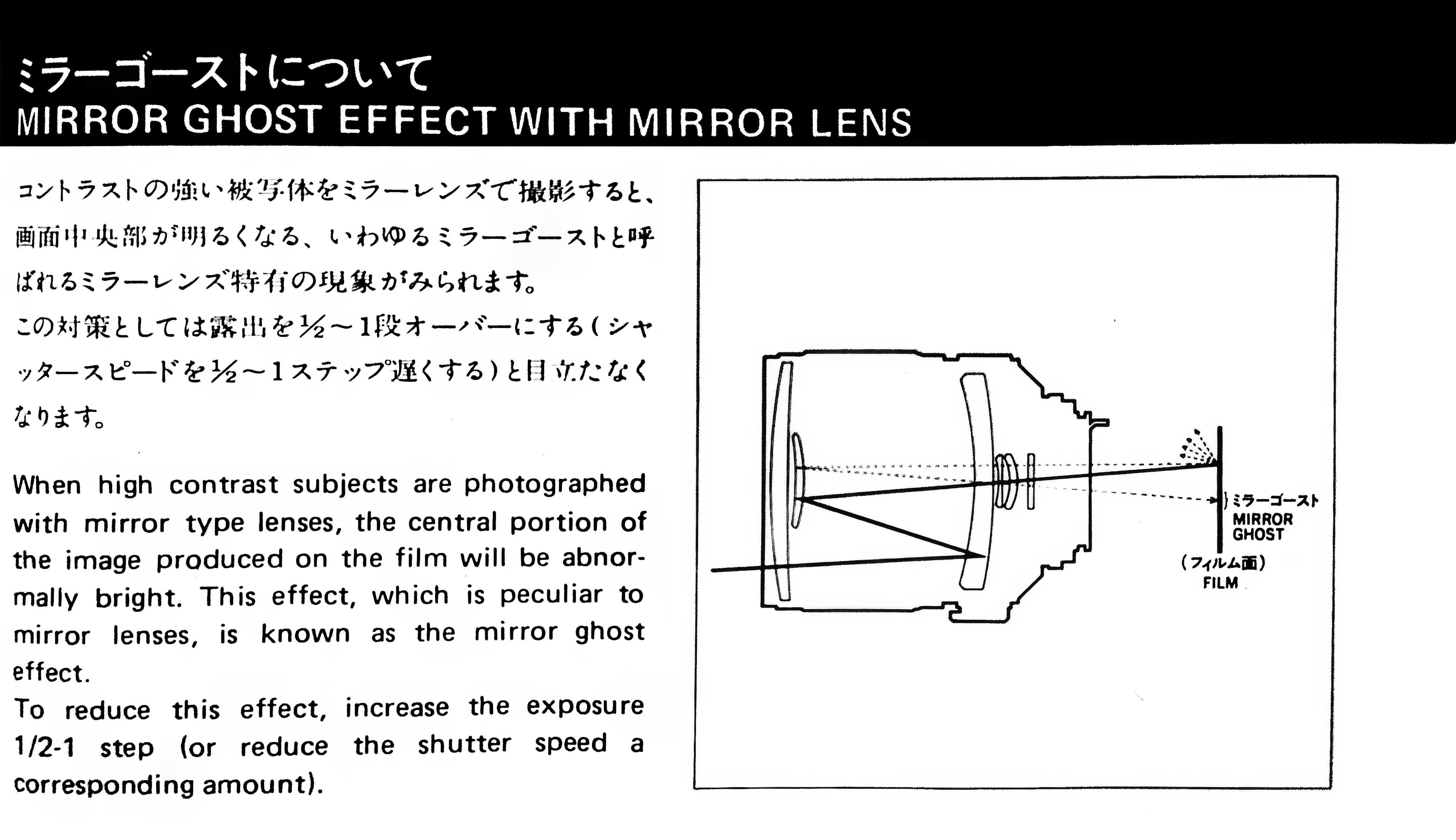
This explanation and the helpful ray trace diagram clearly shows light scattering from the film back up the lens, striking the secondary mirror, and then reflecting back to the film again. This agrees perfectly with my understanding of the hot-spot. A later version of this instruction manual omitted this page, and despite Sigma saying it’s a known phenomenon, I have never seen a similar explanation or admission of the problem from another lens maker, other than Vivitar.
The Sigma illustration also explains another complaint photographers had about mirror lenses when used on SLR and DSLR cameras: over-exposure. There are many forum discussions about the need to compensate exposure downwards. Why would a mirror lens cause overexposure, when the meter is reading the exposure through the lens? The explanation is that the light path changes between metering and the moment of exposure. With most SLR cameras, metering occurs with a fairly dark human pupil at the rear of the optical path, but when the SLR makes the exposure, it flips the mirror up and changes the optical path. Now the more reflective film or sensor is at the rear, and the feedback causes the hot spot and overexposure. In film photography, hot spots are seen to be grayish brown, matching the color of the emulsion.
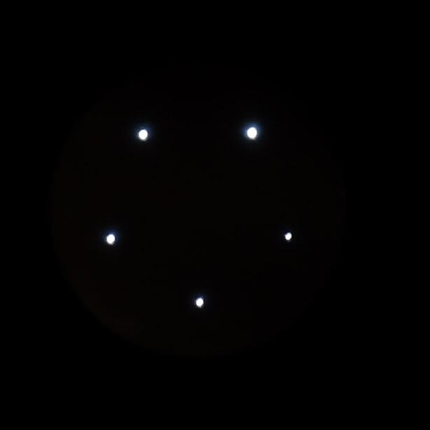
If you’re still not convinced that the mirror lens hot spot is a reflection off the sensor, I have more evidence to consider. While studying Airy disk diffraction patterns, I made some mirror lens photographs of artificial stars in a completely dark basement. The following image has five artificial stars of different sizes; my artificial star is actually an array of five tiny holes bored through a sheet of metal placed at the front of a strong LED flashlight. I used a Sony AF 500mm f8 mirror lens to make this image.
Here’s what happens if I boost the image contrast. Even in the most favorable lighting, where the only source of light is an artificial star and there is no other stray light, there’s a ghost image. This cannot be stray light, diffraction, or vignette. It can only be a reflection off the secondary mirror. Note that the color of the ghost image is magenta: the same as the sensor in the Sony camera I used to make this image.
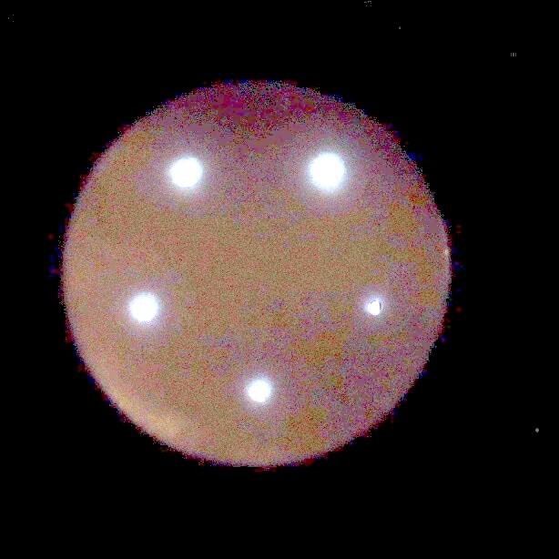
The mirror ghost effect is real, and it’s definitely caused by light reflecting off the sensor/film and again off the center of the secondary mirror. It is distinct from, and additive to, other issues such as diffraction, vignette, and unwanted stray light from the front.
I believe that the severity of the effect is design-specific. Lenses are demonstrably different in the amount and unevenness of hot-spot ghosting they produce; the Vivitar Solid Cat lenses are among those with less garish ghosting, as is the Canon FD 500mm f/8 Reflex. The second-generation Reflex-Nikkor 500mm f/8 tends to have a pretty bright hot spot. I think multiple factors contribute to this variability, but in simplest non-technical terms, I think one of the major factors is how large the sensor’s reflection appears to the sensor. In other words, when you look in the rear of one of these lenses, your reflected face appears to be some size and distance away. The larger and closer it appears, I think, the worse the hot-spot ghosting tends to be.
Proving the Existence of the Mirror Lens Dead Spot
Having satisfied myself that I’d found the cause of the hot spot, I thought I knew the solution, too. As mentioned previously, I intuitively understood that the area reflecting what’s behind the lens is also a dead spot, not reflecting any light rays from the front of the lens. However, before I assumed this to be the case, I wanted to confirm it.
The first way I confirmed the existence of a dead spot is to examine ray-traces of optical diagrams. These are not available for most lenses, or not in the necessary level of detail, but there are enough in patents and other sources to do a broad survey. These diagrams are often messy and hard to read, so instead of actual diagrams, I’ve drawn a representative pseudo-trace diagram that’s similar to real ones for Cassegrain designs, but easier to read. (It’s not accurate, it’s just meant to illustrate general principles.)
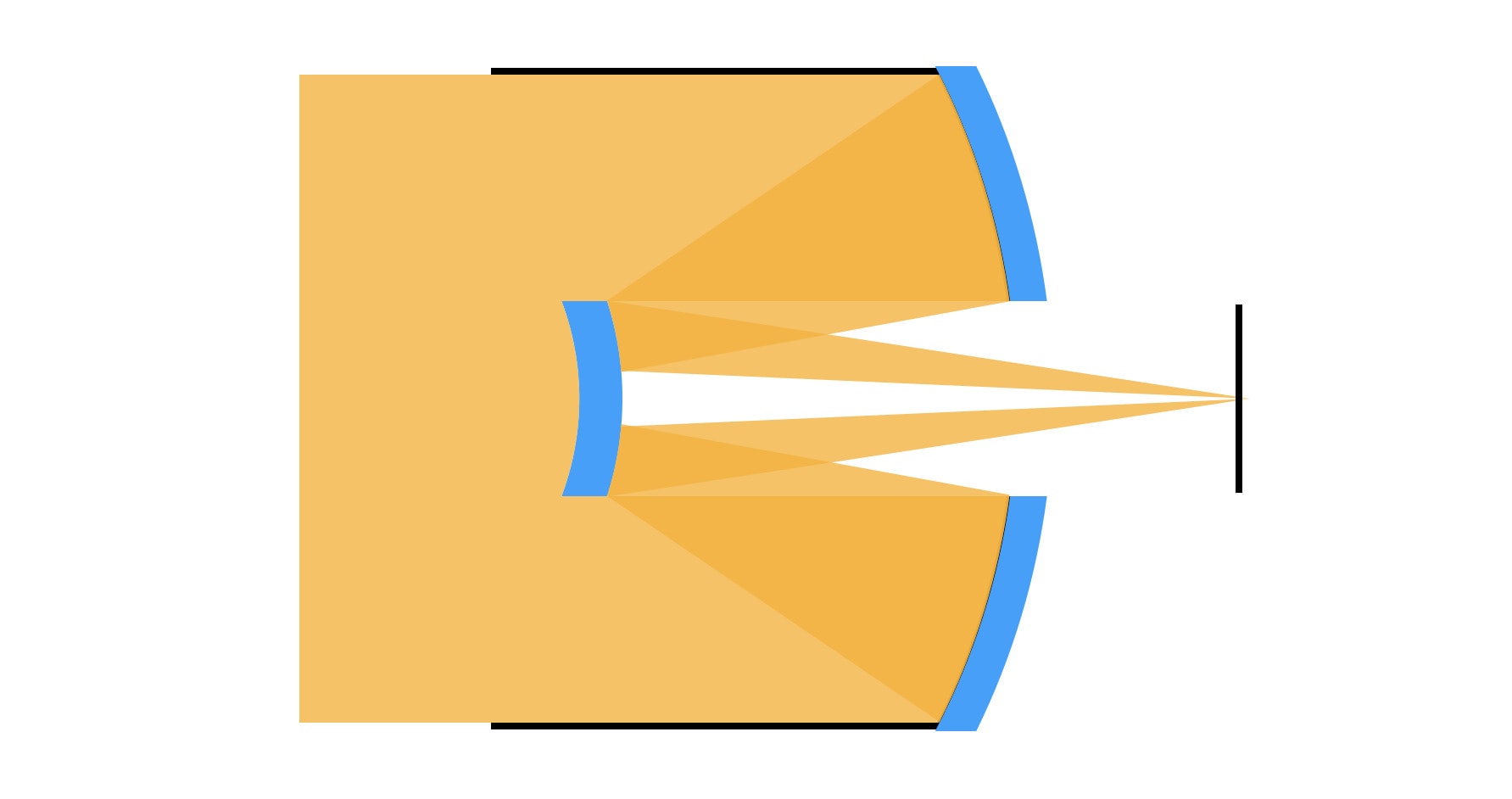
This diagram shows a beam of light entering from the left and reflecting twice from curved mirrors, ending at an image plane on the right. The important point is that the beam of light never strikes the center of the secondary mirror. This is the dead spot (and also the cause of the ghosting).
In the course of examining scores of mirror lens and telescope ray-trace diagrams, I’ve never found one without that dead spot. This is not to say designs without dead spots don’t exist; I can’t convince myself of that. I just haven’t found one. In most lenses, in fact, only a fairly narrow ring at the edge of the secondary seems to participate in the light path. Lenses vary, but a typical dead spot seems to be about 50% of the radius of the secondary.
There’s a dead spot in Newtonian telescopes, too. If you ray-trace a Newtonian scope in the same way as the Cassegrain above, it looks something like the following image.
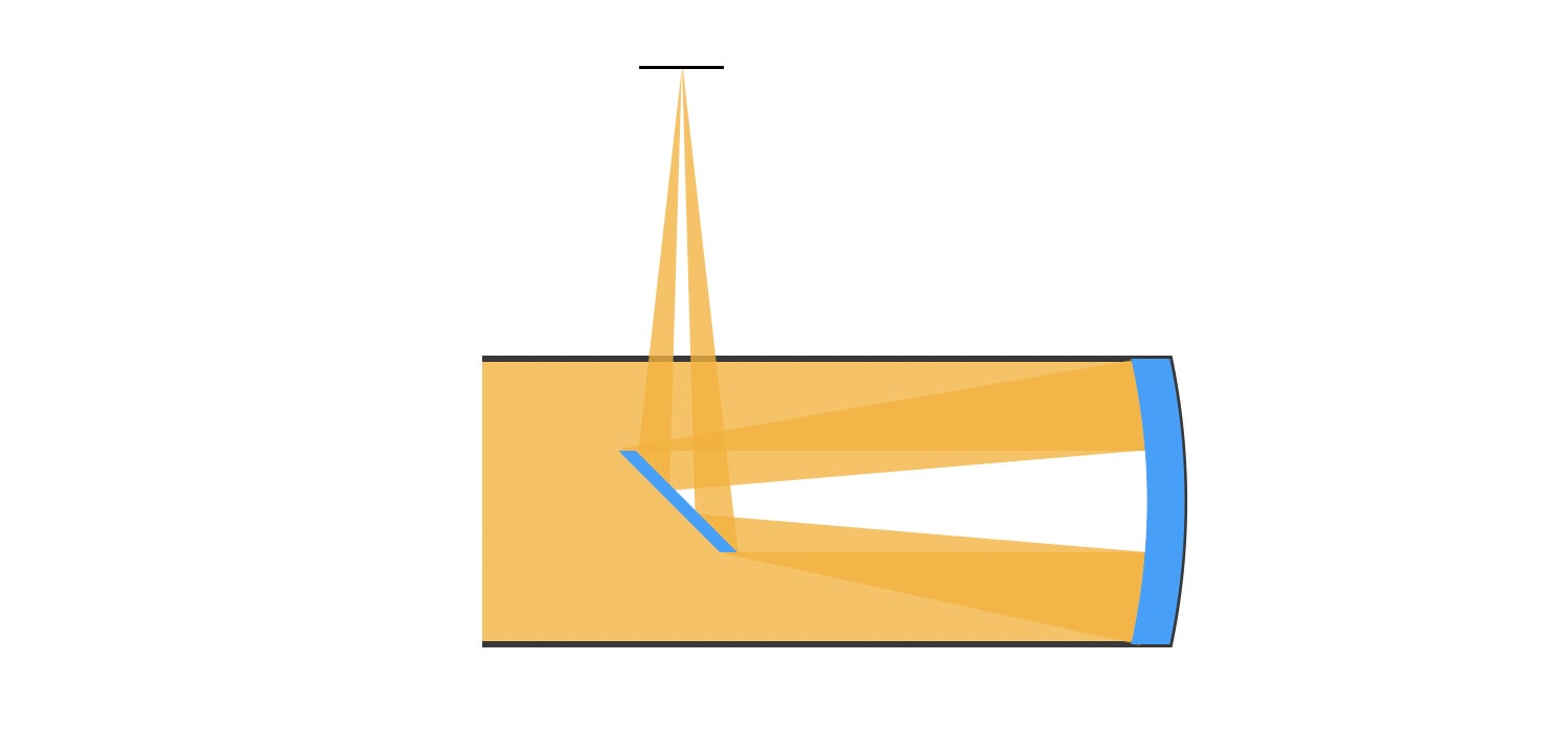
Therefore, Newtonians have a dead spot on the primary mirror. In fact, I am not the first person to notice this. In Astronomy Hacks by Robert Bruce Thompson and Barbara Fritchman Thompson, Hack #33 entitled “Center-Spot Your Mirror,” the authors discuss how to mark the exact center of the primary mirror to facilitate collimating the scope, and in a sidebar they note:
Don’t worry about the center spot affecting the image. The center of the primary mirror, where the center spot is applied, is shaded by the secondary mirror. The shaded center of the primary mirror never “sees” star light, so any marking there has no effect on image quality.
If you look into a Newtonian’s eyepiece from a little distance, you can see a reflection of your own eye, just like looking into the rear of a Cassegrain telescope or mirror lens. This reflection comes from exactly the same spot on the primary as the dead spot is located. It’s a variation on the same theme: Newtonians have a dead spot that creates ghost images, too—except it’s on the primary, not the secondary.
In addition to dead spots on the mirrors, there are dead spots at other locations in many lens designs. For example, the following diagram from Patent US20200218055A1 appears to show a dead spot on the secondary, as well as a dead spot within the corrective optics between the secondary and the image sensor. Most of the corrective optics are apparently only doing useful work at their perimeter. It is not always possible to be sure that a diagram such as this represents every possible ray path, so I could be incorrect about this specific example. However, there are many examples similar to this in which the shadow of the secondary seems to reappear as a hollow core later in the light path.
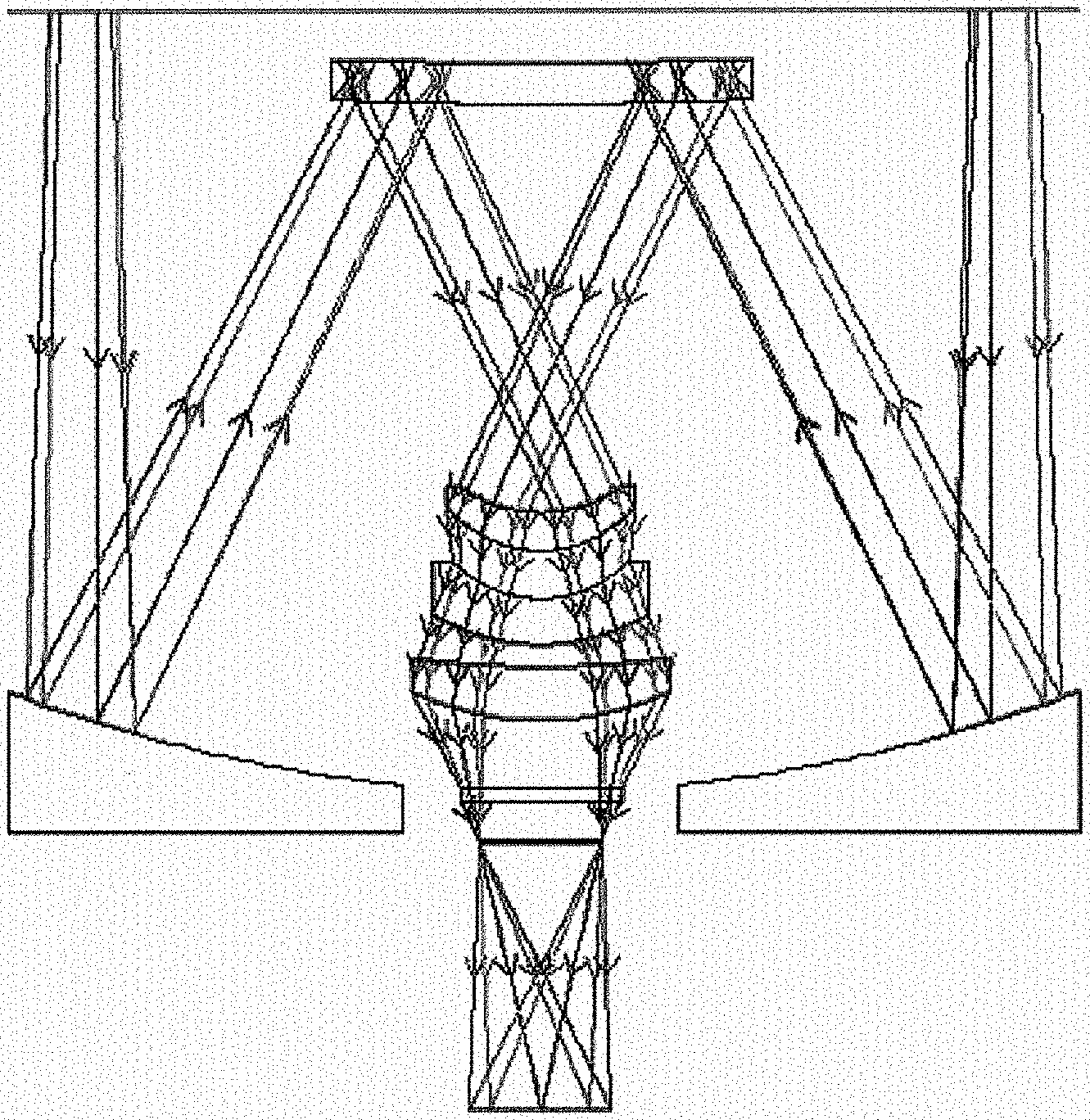
A Gregorian telescope is another common reflecting scope design similar to a Cassegrain, but with a concave secondary mirror; like the Cassegrain, this secondary has both a dead spot and ghost-forming spot at its center. Gregorians create a real image partway through the image path as well as at the typical point of observation behind the optic. This opens interesting possibilities for blocking ghost images and taking advantages of the dead spots.
Here’s another ray-trace diagram from a multi-mirror telescope design, from the paper All Spherical Catadioptric Gregorian Optical Designs for Meter Class Telescopes. The sensor can clearly see its own reflection in the center of the rightmost mirror, and the ray-trace diagram shows multiple dead spots not traversed by any rays. These diagrams can be tricky, though, because they don’t always show all possible incident light paths. There are clearly areas of the primary mirror that are unused in this diagram, suggesting that the scope is designed for a wider field of view and the ray-trace does not demonstrate the path an off-axis ray will take. This is probably a misleading image in terms of proving the existence and size of dead spots in this specific design. However, it’s illustrative of the general principle I’ve found, that the ghost image is usually formed by the sensor seeing its own reflection in the on-axis mirror immediately prior to the sensor in the light path.
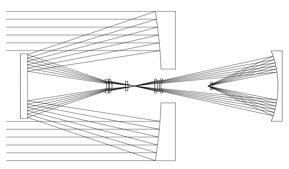
Other designs, such as three-mirror anastigmats, also have easily verifiable dead spots and areas where the sensor can see its own reflection. For example, there’s a famous image of a NASA technician working on the James Webb Space Telescope taking a selfie in the secondary, to verify the scope’s light path. The selfie shows that the telescope’s detector can see itself. That article also embeds an animation of the scope’s light path, from which you can see that there’s a dead spot on the secondary. The scope has a more complex light path, but the same feedback loop can potentially occur (not being an expert, I won’t say it definitely does).
Another way to confirm the existence of a dead spot is to place light-sensitive photographic paper inside the lens, which I’ll describe in a later section; it works but it’s labor-intensive. I have also used a laser pointer to do real-life ray-tracing, both from the front and from the rear of the lens. Again, I can’t rule out the existence of optics without dead spots, but they are present in every one I’ve been able to study in sufficient detail.
Blocking Reflections from the Dead Spot and Testing Results
Having established the cause of mirror lens ghost images as the bright center of the secondary mirror, and determining that a similar portion of that mirror is uninvolved in the lens’s desired operation, it is straightforward reasoning that blocking reflections from that spot should mitigate the problem. Simply blackening the dead spot should help! My next step was to disassemble various lenses of which I own multiple copies, blacken a spot, and then compare the performance of the modified and unmodified lenses. My goal was to see if this helped reduce the unwanted glare, while leaving image quality otherwise unaffected.
My first efforts were on some inexpensive lenses with a strong hot spot, such as the Samyang 500mm f/8 mirror lens. This lens is sold under dozens of brand names, and is easy to get cheaply on the used market. I modified an otherwise seriously defective sample of this lens which I didn’t mind ruining, taking test photos under controlled lighting before and after, holding everything else constant—I did not even remove the camera from the tripod. Here are the test photos, cropped to include only the test target but otherwise unmodified. A 100px square in the center of the dark quadrant at lower left of the target has an average color of RGB(50,50,55) before modification, and RGB(40,40,44) after. This is a very large difference.
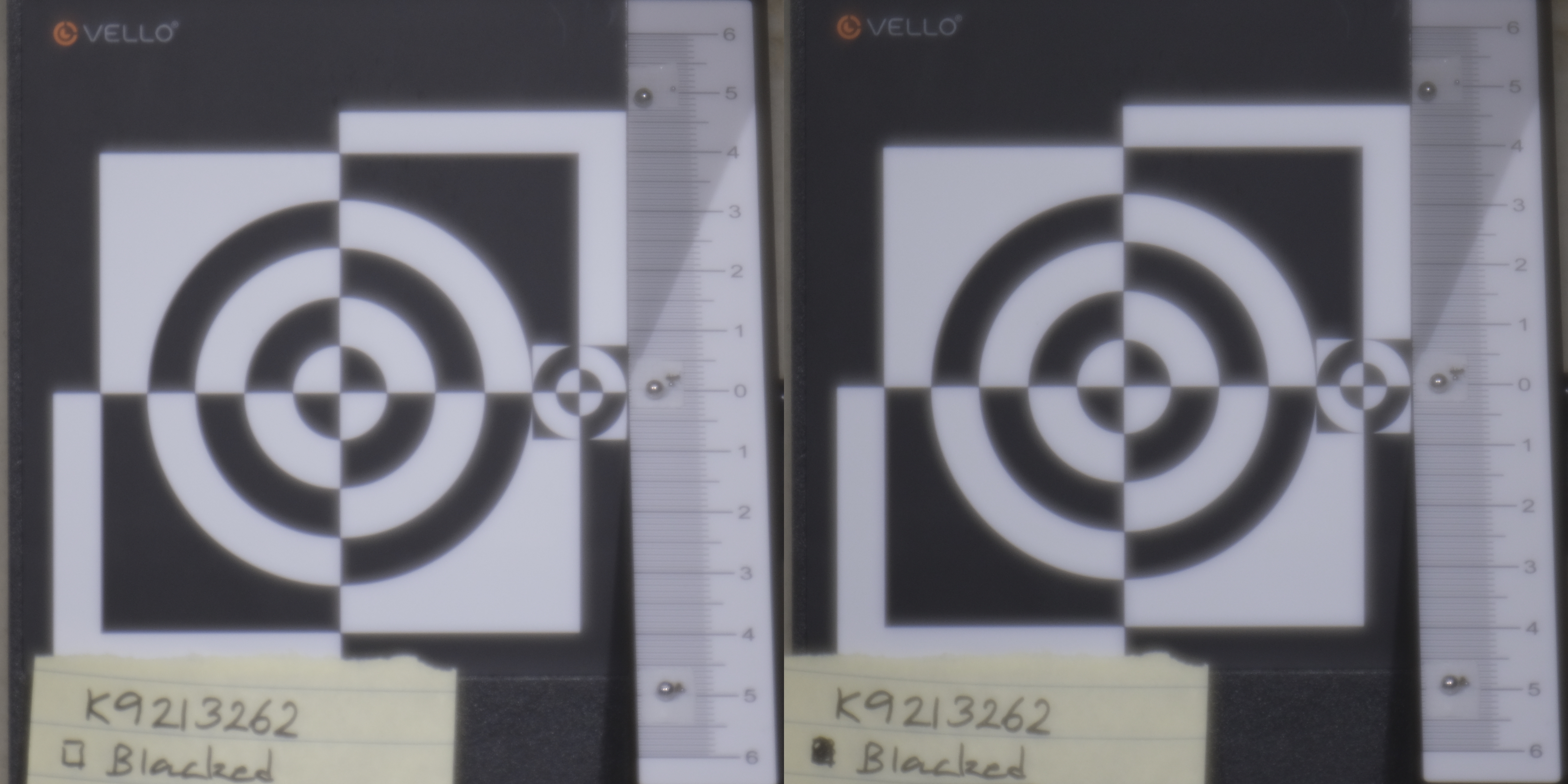
This experiment gave me enough confidence to continue modifying more expensive and hard-to-find lenses, such as the Olympus 500mm f/8, the 3M-5CA Maksutov, the Rubinar 500mm f/5.6, the Tamron 500mm f/8, and the Meade 97D and Celestron C90 scopes among others. The results have varied somewhat depending on how bad the unmodified lens’s hot spot is, but in every case I have observed a real improvement in image quality.
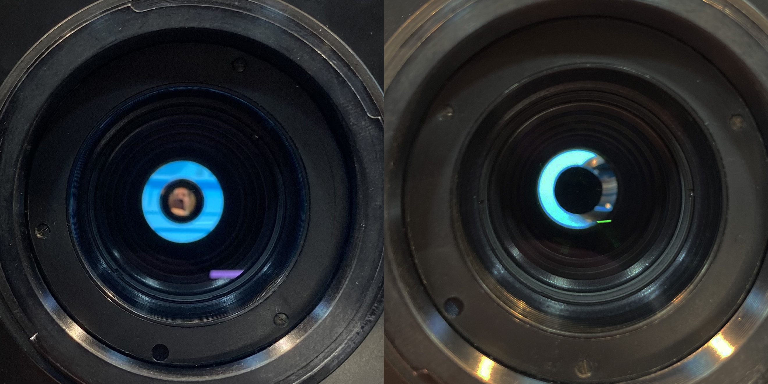
I have tried a variety of ways to actually block the reflections. The main ways are attaching something to the center of the secondary, and painting something on the center of the secondary. At this point I have a lot of experience with what works and doesn’t, but to summarize: placing the lens on a spinning turntable and painting with liquid electrical tape or Tool-Dip (both are nonpermanent and easy to remove cleanly) works well for me, as does attaching a circle of flocking with the same materials. A lens manufacturer could do a better job, but these techniques work. Here’s a relatively crude photo of before and after modification.
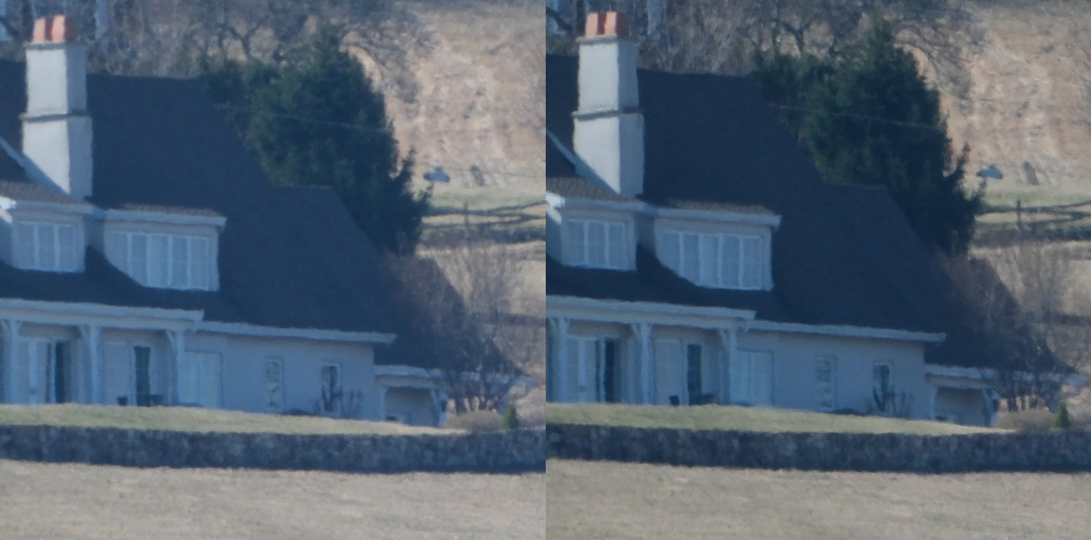
To evaluate the results, I have done careful A/B testing as well as simply using the lenses a lot. Here is an example of a less-controlled A/B test of a real scene with two copies of the 3M-5CA Maksutov, with and without modification. I chose to photograph the scene, a sunlit landscape in the hazy distance, because I recognized that it was the type of image that usually emphasizes the weaknesses of mirror lenses; it has no artistic merit otherwise, and many flaws including the effects of turbulent summer heat. Here is a small crop from a contrasty portion of that landscape image, taken from the midfield, about halfway between the center and corner.
Another way to see the difference is the shape of the image’s histogram. The modified lens produces images with more dark pixels (deeper blacks) and less blue in the midtones. These histograms are of the full landscape scene, not just the crops shown above:

Here’s another example from a high-contrast scene, showing a much more dramatic improvement in overall contrast. Scenes vary, of course, but I get a lot more photos with nice contrasty histograms like this from modified lenses:

I’ve also performed many tests such as making photos of the sky on a clear day. Here is a composite image of a blue sky made with an unmodified Samyang 300mm f/6.3 lens compared to another modified sample, with all other variables held constant. I have artificially changed the contrast and exposure to emphasize the uneven brightness, to the point of causing color bands to appear. Is the modified lens’s central bright spot a true vignette, or is there still some contribution from a ghost image? It is difficult to know. What I can say is that after modification, this lens has become one of my alltime favorites.

In truth, the results of A/B testing usually aren’t all that visually impressive side-by-side, but the experience of actually using the lenses is noticeably different. I am familiar enough with the lenses to know how they usually perform, and I’m continually pleased by being able to use the modified lenses for photos I know would have turned out badly before—for example, when I go birding I simply don’t have to worry so much about what the light is like. Conversely, when I photograph with an unmodified lens, I can’t help noticing how it washes out constantly as I point it at scenes with high contrast. Unmodified lenses only perform well in ideal lighting.
One thing I’ve been curious about is whether the modification will reduce the lens’s brightness. In theory, if the black circle is too large and blocks some of the desired light from the object, that could happen. In actual usage, with the camera set to “matrix” metering, the camera chooses the same exposure, indicating that the modification isn’t blocking useful light. I’d have to do careful ray-tracing to be sure, but I don’t think it is.
Tangentially, making the dead spot nonreflective has ancillary benefits. Stray light from any direction that strikes the dead spot will be absorbed—including stray light from outside the lens’s desired field of view. Even if mirror lenses didn’t form ghost images of the sensor, the dead spot should be blackened for best stray light suppression.
Determining How Much to Blacken
One of the obvious questions is “how big a circle on the secondary should I blacken?” The answer might seem simple, but there are many variations and edge-cases to consider, making it much more complicated. I have tried a number of scientific and ad-hoc methods to take the complexities into consideration, and encouragingly, the answers actually tend to be similar no matter how I arrive at them.
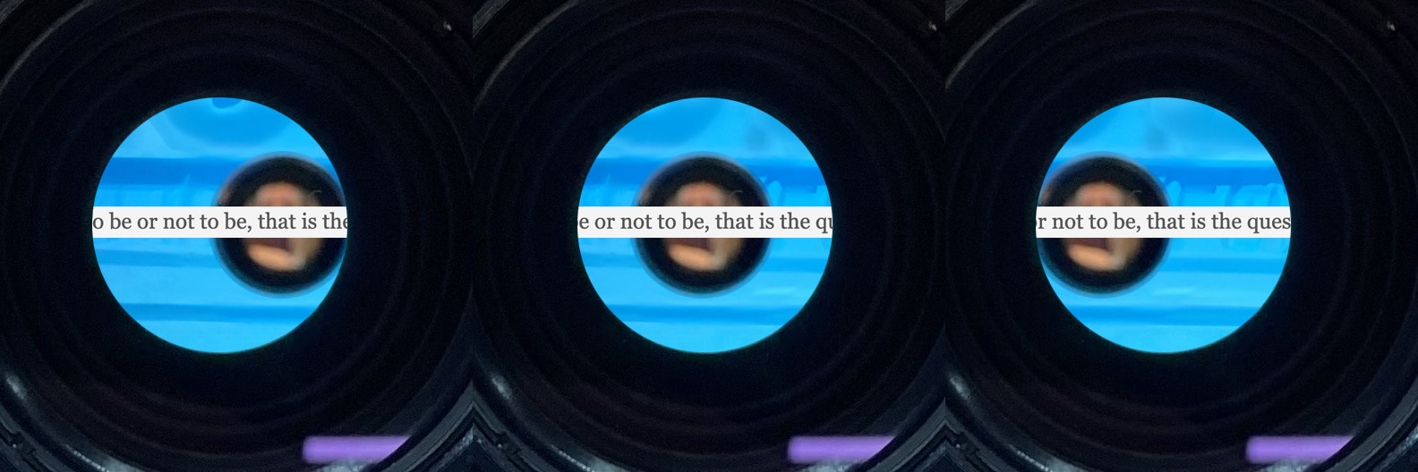
I’ll begin with the method I use today after trying several others. I disassemble the lens by separating the focus helicoid, and place a narrow strip of paper across the center of the secondary. The paper will have some text on it, which I use in lieu of measurement gradations; I find the letters less confusing than markings that all look the same. I usually just cut a strip from a scrap of junk mail or similar, crimp it gently, and wedge it lightly against the secondary baffle. With the paper in place, I reassemble the lens, focus it to its closest focus setting where the primary and secondary are at their most distant, and look at the paper through the rear of the lens. I tilt the lens first to one side, then the other, noting the letters I can see within the circle that reflects light from the rear of the lens. I then disassemble, remove the strip of paper, and measure what I was able to see. I blacken a circle no larger than that on the secondary.
This is a mockup of what the view through the rear of the lens looks like as I’m tilting the lens left, center, and right again. I’m using a mockup because it’s easier to create a clear image than actual photos, and this is important to be able to see clearly.
If I then create a composite of these images of the dead-spot circles as seen from different angles, it might look like the following. I’ve inscribed a small gray circle into the center, and circumscribed a large circle around all of them.
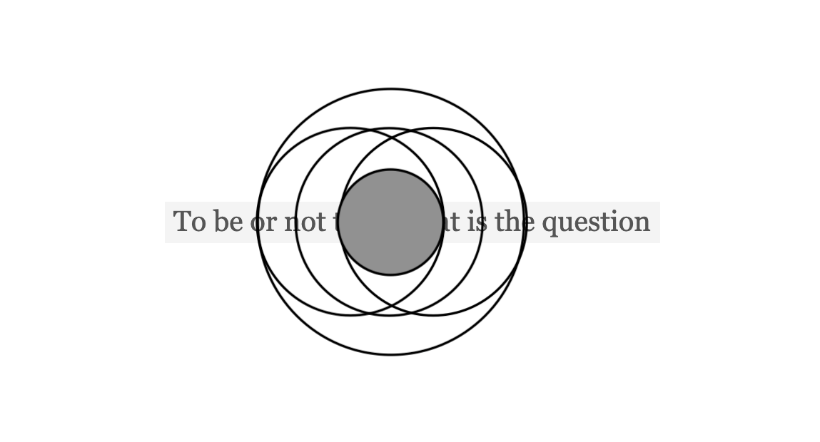
Notice that the dead spot when I’m looking straight into the center of the lens overlaps areas that are actually participating in forming the image when I tilt the lens to the side. Only the gray circle in the very center is truly 100% dead. The area between that gray circle, and the large circle around the whole group, is dead at some angles, but useful at some others. How much of this to blacken is the judgment call one must make.
Other methods I’ve tried include examining ray-trace diagrams, assuming that the dead spot is proportional to the size of the central obstruction, ray-tracing with a laser pointer, and using light-sensitive photographic paper. The ray-tracing was inconclusive because it’s too hard to see precisely where the laser hits the glass, and to know that the laser is tracing not only a valid light path, but a light path at the true periphery of the lens’s intended image circle. Photographic paper was more fun and more fruitful. I disassembled a lens, and then working under a safelight, lodged a scrap of paper across the secondary mirror and reassembled, then capped both ends of the lens. In a darkened room, I lit an area on a distant white wall, then aimed and focused the lens at the lit area and removed the front cap briefly. After developing the paper, I was able to see exactly where the light struck the secondary. The results were not different from other methods I used, but much more tedious, so I haven’t repeated this exercise.
One thing the photographic paper confirmed for me is that just as seen above in my diagrams of tilting the lens side to side, the “working area” of the secondary mirror does not have a crisply defined border, nor does the dead spot have a sharp boundary. The edges of both regions are soft, a penumbra—and they may overlap. Some parts of the secondary are involved in none of the desired rays, some areas reflect all of the desired rays, and there’s an area in between where some of both are true. In modifying lenses, I have chosen to blacken the minimal area—the area that is 100% dead spot under all conditions and doesn’t reflect even a small amount of useful light. As seen in my diagrams above, this clearly does not block 100% of the mirror lens ghosting. However, I have also intuited, and confirmed by experience, that blocking too much of the ghost image tends to block parts of the desired image in ways that are visible, e.g. causing vignette effects, which may be much more obvious in specific conditions such as when the lens is focused to its minimum distance, which in most lenses shortens the focal length and widens the field of view. In addition, if the blackened spot intrudes into the lens’s intended light path, its edge can potentially cause additional diffraction.
Some of the nuances I’ve considered include:
- The size of useful area on the secondary, and the size of dead spot, change as the distance between primary and secondary changes during focusing. At minimum focus, when they’re farthest apart, the dead spot is smaller.
- The most common mirror lens designs that focus by moving the primary and secondary mirrors relative to each other actually change the lens’s effective focal length, and thus its field of view, which changes the size of both the dead spot and ghost-forming spot.
- Lenses of Mangin construction (second-surface mirroring) are more complicated to retrofit for a fix. The black spot cannot be placed directly on the mirrored surface, but is held away somewhat. The same is true of lenses with corrective elements placed at the secondary.
- Lenses with rear-focusing mechanisms, which don’t vary the distance between mirrors to focus, are potentially both simpler because the working area of the secondary doesn’t change during focusing, and more complex because the size of the secondary involved in retroreflections does change. I have not tried to modify any of these yet.
- Zoom mirror lenses, of which there are several examples albeit a small minority of designs, are much more complicated to consider. I have not tried to modify any of these yet.
In addition to the nuances these designs create, there are many more nuances to consider when trying to design ghost-blocking into a lens, instead of painting or sticking it on after the fact. More on this later in this article. Having now explained my efforts to date to my satisfaction, I would like to turn to problems and opportunities I’m aware of for future work, especially when designing a lens to be free of mirror ghost images.
The Importance of Stray Light Control
Astronomers and lens designers know well the importance of reducing stray light in optics in general, but especially in reflecting and catadioptric designs, in large part due to their short physical length relative to their focal length. Most commercially available reflecting telescopes don’t block all the stray light they could, and basic DIY telescope designs can benefit from extensive modifications to block stray light, above and beyond the initial completion of a working instrument.
Browsing astronomy forums for any amount of time will quickly impress upon you the lengths astronomers will go to in order to reduce stray light. Although a non-astronomer might think these efforts are going too far, the astronomers in the forums evidently see the value; there are usually few if any commenters mocking the efforts people make. Astronomers trying to get images free of stray light will add light shields, flock every internal surface of a telescope including oft-overlooked ones, place black blankets on the ground beneath their telescope to prevent starlight bouncing off the ground from entering the scope, wear special hoodies or drape themselves in black cloth while observing, and on and on. As just one example, this cloudynights.com forum thread illustrates the thinking of astronomers, both seasoned and novice. A sample bit of advice from this thread includes “it is essential to do everything you can to suppress scattered light.” There are hundreds of similar threads, easy to find with web searches. Some of them go on for dozens of pages, with hundreds of responses.
It is also easy to find examples of photographic lens designers battling with stray light. The Vivitar Series 1 lens shown before in the advertisement was designed by Juan L. Rayces; in an SPIE Magazine interview, he touted that his design could “completely block stray light that always plagues catadioptric systems.” Nikon’s Thousand and One Nights No.13 mentioned lens designer Tsunashima Teruyoshi’s efforts to design stray light control solutions for the second-generation Reflex-Nikkor 500mm f/8 lens. The Canon Museum website’s entry for the Canon FD 500mm f/8 reflex lens, while brief, devotes a substantial portion of its text to stray light: “to prevent reductions in contrast resulting from inner reflection, which is a problem in reflex lenses, the entire lens is given multilayered coating in addition to meticulous consideration being taken, such as electrostatic flocking being performed inside the lens barrel.” Reading patents provides many more examples of the importance of stray light control in reflex lenses.
And for more high-stakes examples, you can read about the stray light problems the Gaia Space Telescope had, due to some fibers scattering light.
My own work convinced me beyond the shadow of a doubt that the forum quote above is not an exaggeration: it is essential to do everything possible to suppress stray light. The improvement in image quality I have achieved by disassembling cheap lenses and modifying their flocking and baffles is quite dramatic. Again, the better-designed and better-made lenses already take these measures and have little room for improvement in this regard.
I think it is fair to say that the best lens makers are always looking for more effective ways to control stray light, and would adopt any reasonable measures, especially if those were proverbial “low-hanging fruit.”
Design Strategies for Blocking Ghost Images
I believe that there are many ways to incorporate mirror ghost image suppression into the optical design for greatest effectiveness. Additionally, the existence of dead spots in the optical path opens up possibilities to use that space for other purposes. Space and weight are at a premium in many designs, so this is potentially a great advantage. The following is a brief, non-exhaustive, and very general list of possibilities that I have spent some time exploring and believe are fruitful to consider:
- Methods of preventing ghost images by making an area of a mirror non-reflective to block the detector from seeing a self-image.
- In a Cassegrain design, make the center of the secondary mirror non-reflective.
- In a Newtonian design, make the center of the primary mirror non-reflective.
- In an on-axis three-mirror design such as a three-mirror anastigmat, make the center of the tertiary mirror non-reflective.
- In other on-axis designs, it may be possible to make the center of the final mirror in the design that is oriented on-axis to the detector non-reflective.
- Other methods of preventing the detector from seeing a self-image.
- Place a central occlusion or stop in the light path (e.g. in empty space or corrective optics), where rays diverge to the edges of the optics and leave an area around the axis as a dead spot.
- Place a similar but opposite (peripheral) stop in designs such as the Gregorian, where rays instead converge conically to a point at the axis or to a focus, leaving edges as a dead spot.
- Methods of making the ghost image path non-reflective or non-transmissive, other than or in addition to simply blocking ghost reflections; and variations on this approach.
- Place a blackened cone or conical baffle on the center of the appropriate mirror, extending towards the detector; in addition to blocking reflections, it can have the added advantage of filling space in a conical dead spot in the ray path, thus blocking transverse rays through that space and reducing other off-axis stray illumination.
- Place a blackened circle on the surface of the first corrector element in the optical path.
- Place a blackened circle within the optical path, e.g. the opposite of a traditional stop (diaphragm), either in empty space, within an element, or on the surface of an element.
- Remove a circle from (cut a hole in) the center of the appropriate element (e.g. final on-axis mirror, or e.g. a corrector element) and create a light trap.
- Use more advanced methods of selectively blocking stray light such as polarization, collimation and grating, or a Lyot stop, based on the differences in the light paths of the desired image and the ghost image.
- Methods of using the dead spot for other useful purposes.
- Create an opening in the center of the occlusion, and/or enable the occlusion or the center of the occlusion to be easily removed (covered and uncovered) such that the axis of the occluded area can be made reflective/transmissive or not, and therefore used for purposes such as collimation or self-calibration. Even a simple device, such as a smaller circle with a swivel enabling it to be rotated out and back in, would serve.
- Locate a focus mechanism on the dead spot, enabling an internal-only autofocus mechanism moving focus elements attached to the dead spot, leaving the mirrors stationary for ideal aberration correction.
- Ditto, but used for an anti-shake or image stabilization mechanism.
- Methods and strategies for sizing or locating nonreflective or nontransmissive areas.
- Observation: in most mirror lens designs, the shadow from the central obstruction and/or hole in the primary is more sharply defined when the optic is focused to its designed working distance (e.g. infinity), and more diffuse (has a penumbra) when focused at other distances (e.g. macro or close focus).
- Observation: in most mirror lens designs, the shadow from the central obstruction and/or hole in the primary is larger when the optic is focused to infinity, and smaller at close focus distances.
- Strategy: block the maximum possible amount of ghost reflections, even if that blocks some useful light, e.g. areas of the light path that are within the penumbra of the various shadows and thus contain rays that come from objects visible in the optic’s field of view. This strategy minimizes ghost images of the detector, potentially at the cost of making the image dimmer and/or introducing additional diffraction at the edges of the occlusion in the light path.
- Strategy: reverse of the above, occlude the minimum amount, even if that allows some ghost reflections to occur. This strategy maximizes image brightness and likely minimizes additional diffraction-induced loss of contrast, potentially at the cost of allowing some ghost reflections to pollute the image and lower contrast.
- Strategy: compromise on something between the above two extremes.
- Strategy: enable the user or an automatic mechanism to selectively vary the size or location of the stop, occlusion, or blockage in order to tune the optic to the purpose or working conditions as required.
- Method: A device like a conventional aperture diaphragm (iris) could enable this in some designs.
- Method: A device the opposite of a conventional iris could enable this in other designs, by creating a variable-sized central occlusion, with petals that fold out to create a circle, rather than folding to create a circular hole as in a conventional iris.
- Example: maximize brightness when working in dim light.
- Example: minimize ghost reflections when working in bright light, high-contrast scenarios, or in adverse lighting conditions that tend to worsen ghost reflections.
- Example: vary the size of the occlusion or stop based on the distance to which the optic is focused.
- Example: in zoom lens designs, vary the size of the occlusion or stop based on the zoom setting.
- Strategy: prefer designs in which the distance between the mirrors does not change (e.g. rear-focus designs or internal-focus designs), thus avoiding complexities caused by changing shadow sizes or ghost image sizes.
- Strategy: prefer designs in which the ghost image is as small and faint as possible, or as diffused and absorbed as much as possible, instead of or in addition to blocking the ghost image as much as possible.
- Method: move the position of the stop, occlusion, or nonreflective area forwards or backwards in the lens to locate it optimally depending on focus distance or zoom setting.
- Method: ditto, but make the system capable of varying both the position and size.
Conclusion
I hope this article has helped you understand more about the various causes and cures of poor contrast in mirror lenses, and how you might put some of the ideas into practice.
I have been working on this for years, at first skeptical that my idea was original or held any merit, then increasingly spending more time on it as I confirmed my ideas. I’ve read a large amount of literature trying to find evidence that this problem is more widely understood, perhaps in a discipline of which I’m unaware. In the past, many of my inventions have turned out to be reinventions, or misunderstandings that are well-debunked by experts, and I thought that could be the case here as well. To that end, I’ve bought dozens of books on optics and telescopes, read hundreds of US and international patents, and searched academic and scientific databases, journals, and conference proceedings. I’ve found many tangential or distantly related developments—for example, patents discussing better ways to examine the interior of the eye without generating ghost images inside it, or thermal imaging devices suffering from low signal-to-noise ratio due to their own heat emissions. I’ve also found many names for the phenomenon of ghosting (e.g. narcissus rays, self-imaging, and retroreflections), and chased those leads as well, to no avail. No matter the field or context or application, I know of no examples of anyone solving the mirror lens ghost image problem as I’ve done. There are a huge range of reflecting and catadioptric telescope and lens designs: with one, two, or three mirrors or even more; with or without refractive elements; with the image being formed on-axis, off-axis, and beside, inside, or behind the optical assembly; and yet I have not found a single design in which the detector can see its own reflection in the mirrors and there is evidence that the designer took deliberate measures to block it from doing so. It seems like such a simple problem that it’s hard to believe it has been literally and figuratively staring us in the face since the late 1600s. Maybe I’m wrong, but that seems to be exactly what has happened.
The sensitivity of reflector optics to stray light is well-known, and I don’t disparage conventional measures like flocking, baffling, anti-reflective coatings, and special hoodies. Better-performing optics are often differentiated significantly by how well they block stray light. But on the other hand, many a long-running astronomy forum thread has been written about adding flocking and baffles to the smallest, least-likely parts of telescopes to block stray light. I know these efforts are worthwhile, but my experience convinces me that ghost images are certainly one of the most problematic sources of stray light in these lenses and telescopes. Ideally, flock and baffle everything—yes, but that bright useless part of the mirror shining the camera sensor’s glow back at itself should be at the very top of the list. And again, the high priority astronomers place on controlling stray light certainly indicates that if this principle were widely known, everyone would already be doing it. To that end, I’ve written this article to try to raise awareness and start conversations.
I know many astronomers will immediately understand the value of this discovery. Many have made more difficult modifications to their telescopes for smaller gains; I’m sure they will promptly flock the dead spots on their scopes. That is wonderful, and I am eager to see the results. And I’m sure some erstwhile camera tinkerers will also “hack” their mirror lenses as I have done. But I think the really exciting gains will come from designing this technique, or improvements upon it, into optics from the beginning instead of modifying them after the fact. It’s doubtless too late to carry a bucket of black paint into orbit and start dabbing at space telescopes, but perhaps the next one we launch can be that much better.
You can contact the author at pythons_cohos.0r@icloud.com
Selected Bibliography
TODO